QoS-VPP Case
Introduction
This guide provides a step-by-step tutorial for configuring the Quality of Service (QoS) capabilities of the Asterfusion ET2500 Open Intelligent Gateway running AsterNOS-VPP.
What This Guide Will Accomplish
By following this guide, you will learn how to implement progressively advanced traffic control strategies, moving from granular flow control to interface-level management, and finally to complex service level agreements (SLA). The scenarios covered are:
- Phase 1: Bi-directional Flow-Based Policing (Smart Flow Control): Configuring the gateway to intelligently limit high-bandwidth UDP traffic (e.g., video/P2P) while allowing TCP traffic (e.g., office work) to pass at full speed.
- Phase 2: Bi-directional Port-Based Rate Limiting (Hard Limiting): Applying a strict bandwidth limit on a specific physical interface, regardless of traffic type, suitable for tenant management.
- Phase 3: Elastic Bandwidth Management (tr-TCM): Implementing a "Guaranteed + Burstable" bandwidth service using Two-Rate Three-Color Marker (tr-TCM) technology.
Preparation: Building the Basic Network
Before applying QoS policies, we must ensure basic connectivity and NAT are working.
Topology & Planning
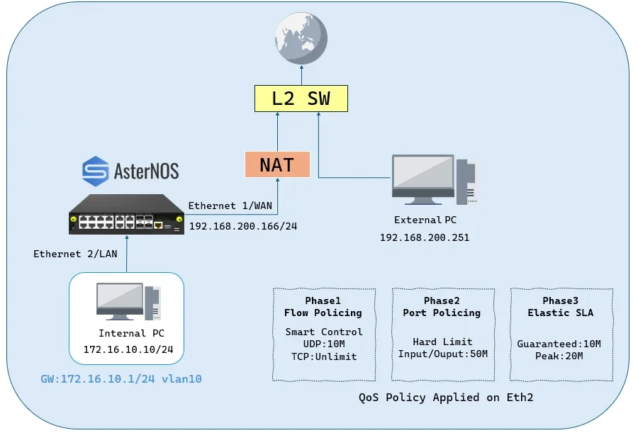
- Lab Components:
Device Type / Operating System | Role in Topology | Key Function in This Guide |
|---|---|---|
ET2500 / AsterNOS | QoS Gateway | Device Under Test (DUT) for QoS configuration. |
Physical PC / Windows | Internal Client | Client PC for generating traffic and testing speed. |
Physical PC / Linux or Windows | Traffic Server | Server in the WAN zone (External PC) running iperf3. |
- Target Configuration Plan:
Device / Logical Interface | IP Address / Subnet | Default Gateway | Notes / Connection Point |
|---|---|---|---|
AsterNOS VM (WAN) | 192.168.200.166/24 | 192.168.200.1 | Connects via Ethernet1 to Upstream Switch |
AsterNOS VM (LAN) | 172.16.10.1/24 | - | Gateway for Internal Client (Ethernet2 in VLAN 10) |
Internal Client PC | 172.16.10.10/24 | 172.16.10.1 | Connects to AsterNOS Ethernet2 |
Traffic Server (External) | 192.168.200.251/24 | 192.168.200.1 | Connects to Upstream Switch |
Configuration steps
Step 1: Configure Interfaces, Routing and NAT
Verification: Ensure the Internal Client can ping the Traffic Server (192.168.200.251).
Phase 1: Bi-directional Flow-Based Policing (Smart Flow Control)
Goal: Limit UDP traffic (e.g., Video/P2P) to 10 Mbps in both Upload and Download directions, while allowing TCP traffic (e.g., Office work) to utilize the full available bandwidth without restriction.
Configuration steps
- Step 1: Define Traffic Behavior Create a behavior that defines the rate limit (CAR) for UDP traffic.
- CIR: 1250 KBps.
- CBS: 100000 Bytes (Burst buffer).
- Step 2: Define Flow Classification (ACLs) Create two ACLs (Ingress and Egress) to identify UDP traffic. TCP and other traffic will match the default permit rule (or you can explicitly add a permit rule). 1. Configure Ingress ACL (Upload Control)
- 2. Configure Egress ACL (Download Control)
- 3. Verify ACL rule

- Step 3: Apply Policies to Interface Bind both ACLs to the LAN interface (Ethernet2) to enforce bi-directional control.
Verification
- UDP Test (Should be Limited): Execute: iperf3 -c 192.168.200.251 -u -b 50M -t 10 -i 1 (Add -R for download test) Expected Result: The bandwidth is strictly limited to ~10 Mbps with high packet loss in both directions.
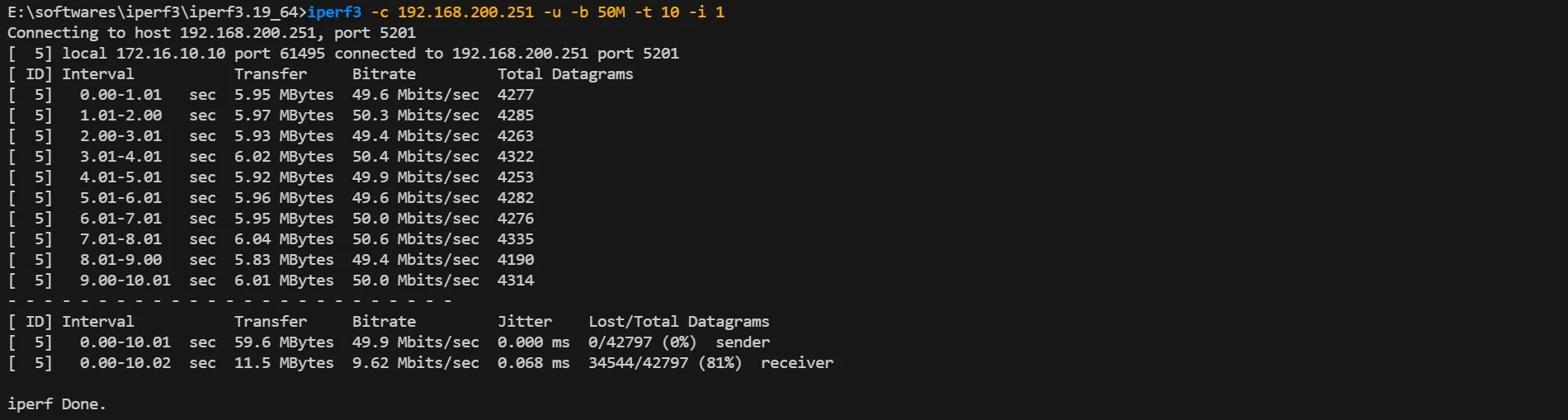
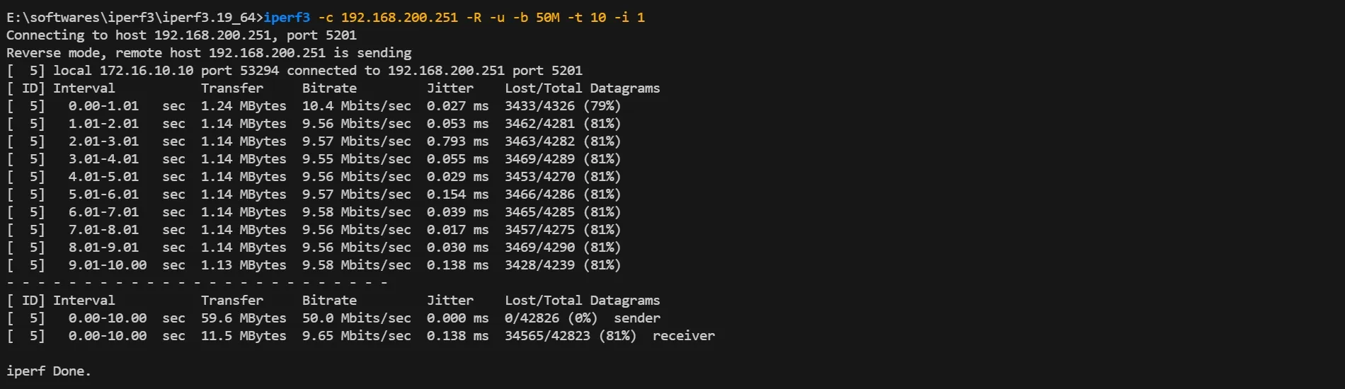
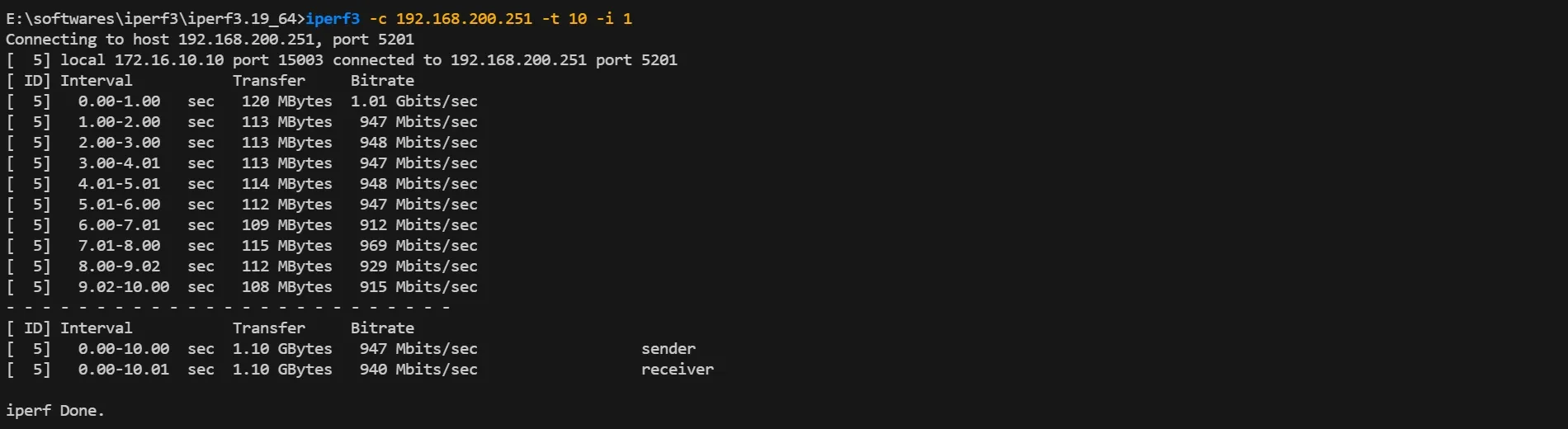
- TCP Test (Should be Unlimited): Execute: iperf3 -c 192.168.200.251 -t 10 -i 1 (Add -R for download test) Expected Result: The bandwidth reaches ~950 Mbps (or line rate), proving that normal office traffic is unaffected.
Phase 2: Port-Based Bi-directional Rate Limiting
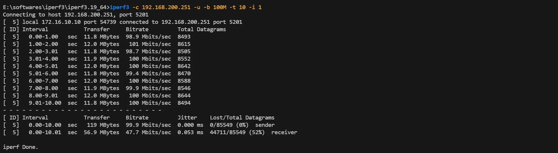
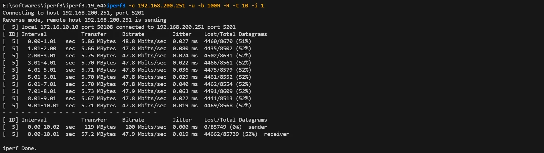
Goal: Limit the total bandwidth of Ethernet2 to 50Mbps in both directions (Upload/Ingress and Download/Egress). This effectively simulates a 50Mbps dedicated line for a tenant.
Configuration steps
- Step 1: Clean Up Previous Configuration
- Step 2: Define Port Limit Behavior
- CIR: 6250 KBps.
- Step 3: Bind to Interface (Both Directions) Bind the behavior to both Ingress (default) and Egress directions to enforce a symmetric speed limit.
Verification
- Upload Test (Ingress Limit): Execute: iperf3 -c 192.168.200.251 -u -b 100M -t 10 -i 1 Expected Result: Bandwidth capped at ~50Mbps.
- Download Test (Egress Limit): Execute: iperf3 -c 192.168.200.251 -u -b 100M -R -t 10 -i 1 Expected Result: Bandwidth is also capped at ~50Mbps.
Phase 3: Elastic Bandwidth Management (tr-TCM)
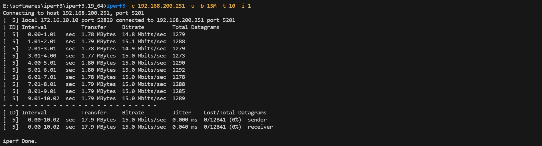
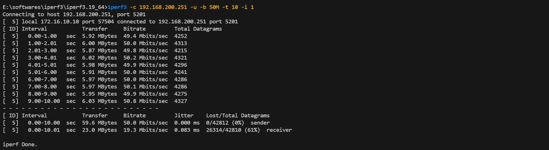
Goal: Implement a flexible SLA policy where the user is guaranteed 10Mbps (CIR) but allowed to burst up to 20Mbps (PIR). Traffic exceeding 20Mbps is dropped.
Configuration steps
- Step 1: Clean Up Previous Configuration
- Step 2: Define Two-Rate Three-Color Marker (tr-TCM)
- CIR (Guaranteed): 1250 KBps.
- PIR (Peak): 2500 KBps.
- PBS: 200000 Bytes (Peak buffer, must be > CBS).
- Step 3: Bind to Interface
Verification
- Test "Yellow" Zone (Elastic Burst): Execute: iperf3 -c 192.168.200.251 -u -b 15M -t 10 -i 1 Expected Result: Bandwidth reaches 15Mbps (exceeding CIR but within PIR), showing allowed burst.
- Test "Red" Zone (Peak Cap): Execute: iperf3 -c 192.168.200.251 -u -b 50M -t 10 -i 1 Expected Result: Bandwidth is strictly capped at ~20Mbps (PIR limit).
Summary of QoS Policies
After configuring the scenarios above, you can verify all created traffic behaviors in the system database. This confirms that the rate-limiting parameters (CIR, PIR, CBS, PBS) are correctly defined.
- Command:
- Output Verification: Ensure that the modes (SR_TCM vs TR_TCM) and rate values match your design requirements.

Conclusion
This guide has verified the comprehensive QoS capabilities of AsterNOS-VPP, enabling granular traffic management from basic port limits to complex flow-based and elastic bandwidth strategies.