Multicast PIM-ASM/SSM Configuration Guide
Introduction
This guide provides a comprehensive, step-by-step tutorial for establishing IPv4 Multicast networks on the Asterfusion Open Intelligent Gateway. By leveraging the high-performance VPP data plane, you will learn how to build multicast routing architectures that are both highly efficient and scalable for enterprise and data center environments.
What This Guide Will Accomplish
By following this guide, you will learn how to deploy robust multicast architectures. The configuration scenarios are structured into two distinct phases:
Phase 1: Establish ASM Underlay
- Scenario 1: Basic PIM-SM with Static RP Establishing a foundational PIM-ASM network using OSPF as the underlay routing protocol with a central Rendezvous Point.
- Scenario 2: Multicast over BGP Deploying PIM-ASM over a BGP underlay to validate advanced RPF checks within a typical Spine-Leaf topology.
Phase 2: Advanced Capabilities
- Scenario 3: PIM-SSM Built directly upon the underlay established in Phase 1, this scenario demonstrates how to migrate to a highly efficient, RP-less architecture using IGMPv3 and explicit (S, G) tree building.
Scenario 1: Basic PIM-SM with Static RP
Scenario Overview
In this scenario, we establish a standard PIM-SM domain without using Loopback interfaces. The Spine's Ethernet1 IP (10.0.1.2) serves as the Static RP for the entire domain.
Device Roles:
- Source DR (Leaf1): Gateway for the Multicast Source.
- RP (Spine): The central Rendezvous Point. Its downlink interface IP (10.0.1.2) is used as the RP address.
- Receiver DR (Leaf2): Gateway for the Receiver, running IGMPv3.
Network Topology Plan
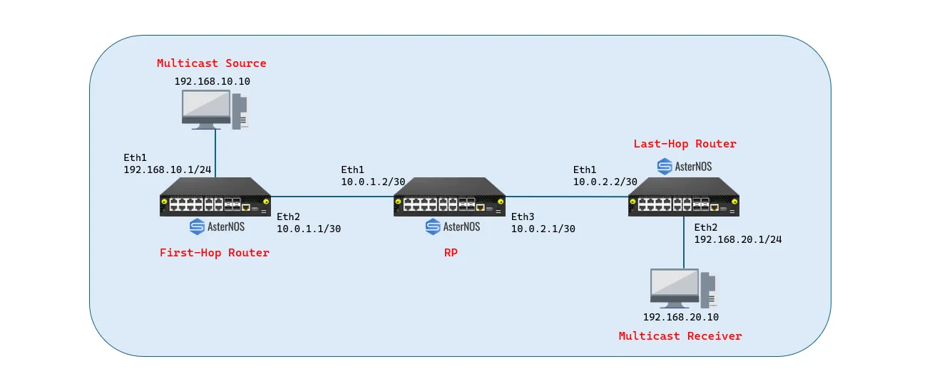
Role | Device | Interface | IP Address | Function |
|---|---|---|---|---|
Source DR | Leaf1 | Ethernet 1 (Downlink) | 192.168.10.1/24 | Connects to Source PC |
Ethernet 2 (Uplink) | 10.0.1.1/30 | Connects to Spine (Ethernet1) | ||
RP / Spine | Spine | Ethernet 1 (Downlink) | 10.0.1.2/30 | Connects to Leaf1 (RP Address) |
Ethernet 3 (Downlink) | 10.0.2.1/30 | Connects to Leaf2 | ||
Receiver DR | Leaf2 | Ethernet 1 (Uplink) | 10.0.2.2/30 | Connects to Spine (Ethernet3) |
Ethernet 2 (Downlink) | 192.168.20.1/24 | Connects to Receiver PC |
Configuration Steps
Configure Source DR (Leaf1)
Leaf1 connects to the Source PC via Ethernet 1 and the Spine via Ethernet 2. The critical step is enabling the unknown-multicast trap to ensure the first multicast packet is sent to the CPU for PIM registration.
Configure Spine (RP)
The Spine acts as the Rendezvous Point. We use the IP address of Ethernet 1 (10.0.1.2) as the RP address for the entire network.
Configure Receiver DR (Leaf2)
Leaf2 connects to the Spine via Ethernet 1 and the Receiver PC via Ethernet 2. IGMPv3 is explicitly enabled on the receiver-facing interface.
Verification
Control Plane Verification
- Verify PIM Neighbors (on Spine)

- Verify RP Mapping (Any Device)


Data Plane Verification
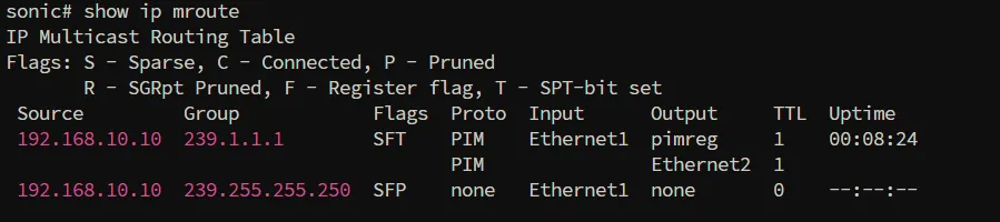
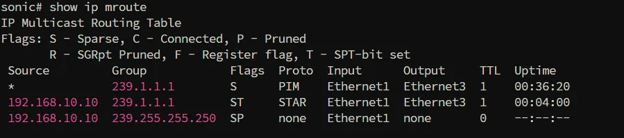
Send multicast traffic from Source (192.168.10.10) to Group (239.1.1.1) and have the Receiver join the group.
- Leaf1 (Source DR) - Verify Registration
- Spine (RP) - Verify Forwarding Tree
- Leaf2 (Receiver DR) - Verify Reception

Scenario 2: Multicast over BGP (Data Center Architecture)
Scenario Overview
This scenario replicates a typical Data Center Spine-Leaf architecture using BGP as the underlay routing protocol. Unlike OSPF, BGP does not automatically flood routing information. This scenario validates that the AsterNOS PIM stack can correctly perform RPF (Reverse Path Forwarding) checks based on BGP routing tables.
Key Changes:
- Underlay Protocol: Replaced OSPF with BGP.
- Routing Logic: Leaf2 must learn the RP address via BGP to send PIM Join messages.
Configuration Steps
Configure Source DR (Leaf1)
Leaf1 connects to the Source (192.168.10.10). It must advertise the source subnet into BGP so the Spine knows where the multicast source is located.
Configure Spine (RP)
Configure Receiver DR (Leaf2)
Leaf2 (AS 65002) connects to the Receiver. It learns the RP route via BGP.
Verification
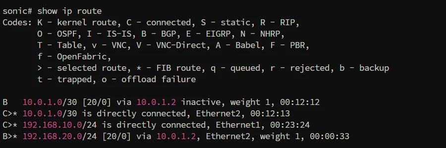
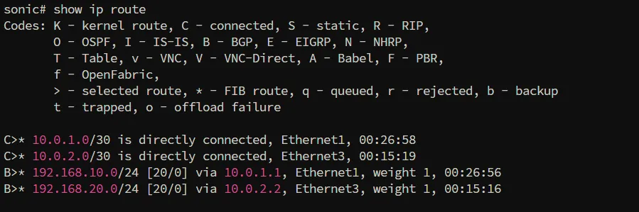
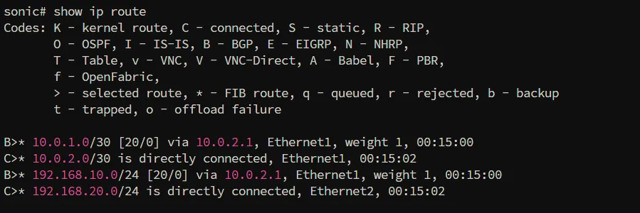
Verify Underlay Routing (BGP)
- Leaf1:
- RP:
- Leaf2:
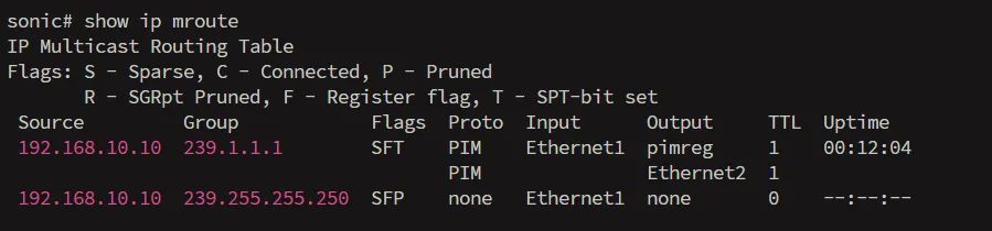
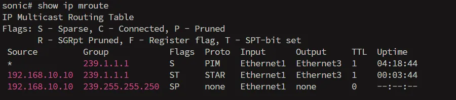
Verify Multicast Routing (PIM over BGP)
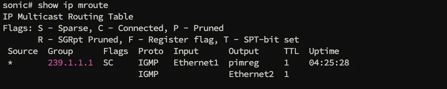
Check the multicast routing table after the receiver joins the group.
- Leaf1:
- RP:
- Leaf2:
Scenario 3: PIM-SSM (Source Specific Multicast)
Scenario Overview
This scenario demonstrates the transition from ASM to PIM-SSM. In this mode, the RP is eliminated, and the multicast distribution tree is built directly from the receiver to the source using IGMPv3.
Configuration Steps
This configuration assumes the physical underlay (Scenario 1 or 2) is already functional.
Upgrade to IGMPv3(Leaf2 Only)
To process Source-Specific joins, the receiver-facing interface on Leaf2 must be upgraded to IGMP version 3.
Global RP Cleanup (All Devices)
The core of SSM is the complete absence of a Rendezvous Point. You must remove the static RP configuration from Leaf1, Spine, and Leaf2 to tear down the ASM shared tree mechanism.
Note: (No further router configuration is needed. The network is now ready for SSM.)
Flow Triggering Requirements
To establish the SSM Shortest Path Tree (SPT), the following conditions must be met by the end-stations:
- Source Side: Outbound multicast traffic must target a destination IP within 232.0.0.0/8.
- Receiver Side: The host must issue an IGMPv3 Membership Report that includes the specific Source IP (192.168.10.10) and Group IP.
Verification
Verify IGMPv3 Join
Check the IGMP groups on Leaf2 to ensure the receiver has successfully sent an IGMPv3 Source-Specific Join.

Verify PIM-SSM Routing Table
Check the multicast routing table on Leaf2 to confirm the Shortest Path Tree (SPT) has been established directly to the source.

Conclusion
This guide has verified the comprehensive multicast routing capabilities of AsterNOS, enabling highly efficient traffic distribution across diverse topologies. The completed scenarios demonstrate that AsterNOS provides the essential flexibility required for modern networks, seamlessly supporting both traditional PIM-ASM and advanced, RP-less PIM-SSM architectures.