Best Practices for Small-Scale AI Compute Backend Fabric
Preface
This guide provides a detailed introduction to the standardized networking solution, configuration guidance, and maintenance manual for small-scale AI computing backend fabric. The solution implements a single-tier Clos network using Asterfusion data center switches, based on Rail-only architecture.
Target Audience
Intended for solution planners, designers, and on-site implementation engineers who are familiar with:
- Asterfusion data center switches
- RoCE, PFC, ECN, and related technologies
Overview
The Rail-only architecture is the ideal design for small-scale AI backend fabric.
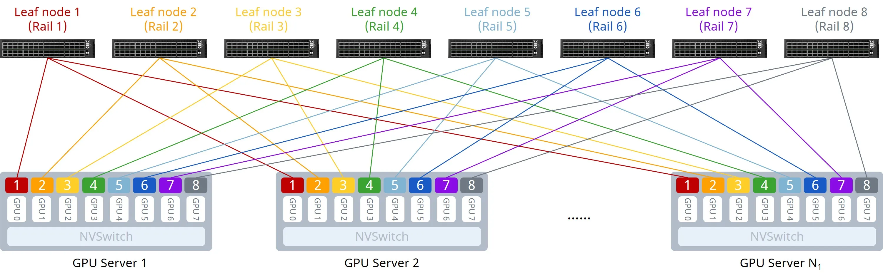
As shown in the figure above, the Rail-only architecture adopts a single-tier network design, physically partitioning the entire cluster network into 8 independent rails. Communication between GPUs of different nodes is intra-rail, achieving single-hop connectivity.
Compared to the traditional Clos architecture, the Rail-only architecture eliminates the Spine layer. By reducing network tiers, it saves on the number of switches and optical modules, thereby reducing hardware costs. It is a low-cost, high-performance network architecture specifically tailored for large AI model training in small-scale compute clusters.
Typical Configuration Example
Network Topology
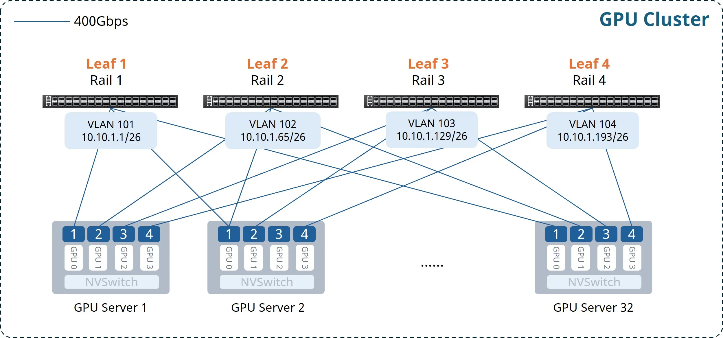
This example illustrates an AI cluster consisting of 32 compute nodes (128 GPUs total, 4 per server), with 4 CX732Q-N switches deployed as Leaf nodes. The key design principles are summarized as follows:
- Each GPU connects to a dedicated NIC; NICs follow the "NIC N to Leaf N" rule. Independent subnets per Rail.
- Single-tier Clos architecture.
- Easy RoCE enabled on Leaf switches.
The Gateway VLAN IP address planning is as follows:
Table 1: Gateway VLAN IP Address Planning
Device Name | VLAN | Gateway IP Address |
|---|---|---|
Leaf1 | 101 | 10.10.1.1/26 |
Leaf2 | 102 | 10.10.1.65/26 |
Leaf3 | 103 | 10.10.1.129/26 |
Leaf4 | 104 | 10.10.1.193/26 |
Configuration Overview
Table 2: Configuration Overview
Task | Configuration Roadmap |
|---|---|
Configure Leaf Switch | (Optional) Configure NIC-side interface breakout |
Configure Gateway VLAN and IP address | |
Enable Easy RoCE |
Configuring Leaf Switches
(Optional) Configure NIC-side Interface Breakout
When connecting 400G NICs to CX864E-N switches, split each 800G port into two 400G interfaces.
Table 3: Interface Breakout Configuration
Step | Leaf1 |
|---|---|
Enter global configuration mode | configure terminal |
Configure breakout for 800G interfaces | interface range ethernet 0/0-0/504 breakout 2x400G[200G] ! |
If the current version does not support batch configuration: | interface ethernet 0/0 breakout 2x400G[200G] ! ...... |
After completing the configuration, verify the interface status using the show interface summary command.
Configure Gateway VLAN and IP Address
Table 4: Configuring VLAN and Interface IP Addresses
Step | Leaf1 |
|---|---|
Configure hostname. | hostname Leaf1 |
Enter global configuration mode. | configure terminal |
Create Gateway VLAN and configure IP. | vlan 101 ! interface vlan 101 ip address 10.10.1.1/26 exit ! |
Add interfaces to the VLAN. | interface range ethernet 0/0-0/248 switchport access vlan 101 ! |
If the current version does not support batch configuration: | interface ethernet 0/0 switchport access vlan 101 ! ...... |
Verify VLAN configuration using the show vlan summary command.
Enable Easy RoCE
The CX-N series switches support queues 0-7 (8 queues in total). Queue 3 and queue 4 are lossless (supporting up to two lossless queues), while others are lossy.
The default template uses system-default DSCP mapping. PFC and ECN are enabled for queue 3 and queue 4, and Strict Priority (SP) scheduling is set for queues 6 and 7.
When creating a template, you can specify three parameters:
- cable-length: Specifies the cable length, affecting PFC and ECN parameter calculations. Options: 5m/40m/100m/300m. If the exact length is unavailable, choose the closest value (e.g., choose 5m for a 10m cable).
- incast-level: Specifies the traffic Incast model, affecting PFC parameters calculation. Options: low (e.g. 1:1) / medium (e.g. 3:1) / high (e.g. 10:1). Low is typically used for GPU backend fabric.
- traffic-model: Specifies the business type: throughput-sensitive, latency-sensitive, or balanced. This affects ECN parameters calculations. Options: throughput/latency/balance. balance and throughput are typically used for GPU backend fabric.
If the provided lossless RoCE configuration does not fully suit your scenario, refer to RoCE Parameter Adjustment/Optimization for fine-tuning.
Table 5: Enabling Easy RoCE
Step | Leaf1 |
|---|---|
(Optional) Modify lossless queues; requires save and reload to take effect. | no priority-flow-control enable 3 no priority-flow-control enable 4 priority-flow-control enable queue-id write reload |
Select Easy RoCE template and apply to all interfaces. | qos roce lossless cable-length 5m incast-level low traffic-model throughput qos service-policy roce_lossless_5m_low_throughput |
Verify RoCE configuration using the show qos roce command.
Maintenance
RoCE Parameter Adjustment/Optimization
When default configurations are insufficient, use the following commands to optimize performance.
Modify DSCP Mapping
Table 6: Modifying DSCP Mapping
Step | Command |
|---|---|
Check running-config for DSCP map name | show running-config |
Enter global configuration mode | configure terminal |
Enter DSCP map configuration view | diffserv-map type ip-dscp roce_lossless_diffserv_map |
Map specific DSCP to COS value | ip-dscp dscp_value cos cos_value |
Map all DSCP to a default COS | default cos_value |
Use system default DSCP mapping | default copy |
NOTE: The COS value represents the Queue ID the packet is mapped to.
Modify Queue Scheduling Policy
If the interface has been bound to a lossless RoCE policy, unbind it before modifying.
Table 7: Modifying Queue Scheduling Policy
Step | Command |
|---|---|
Check running-config for policy name | show running-config |
Enter global configuration mode | configure terminal |
Enter lossless RoCE policy view | policy-map roce_lossless_name |
Configure SP mode scheduling | queue-scheduler priority queue queue-id |
Configure DWRR mode scheduling | queue-scheduler queue-limit percent queue-weight queue queue-id |
Adjust PFC and ECN Thresholds
ECN thresholds are adjusted via min_th, max_th, and probability:
- min_th sets the lower absolute value for ECN marking (Bytes).
- max_th sets the upper absolute value for ECN marking (Bytes).
- probability sets the maximum marking probability [1-100].
PFC thresholds are adjusted via the dynamic threshold coefficient dynamic_th:
\text{PFC threshold} = 2^{\text{dynamic\_th}} \times \text{remaining available buffer}Other parameters can remain unchanged during modification.
Recommended values for CX864E-N:
- PFC dynamic_th: 1, 2, 3
- WRED min (Bytes): 1,000,000 / 2,000,000 / 3,000,000
- WRED max (Bytes): 8,000,000 / 10,000,000 / 12,000,000
- WRED probability (%): 10, 30, 50, 70, 90
Recommended values for other models:
- PFC dynamic_th: 1, 2, 3
- WRED min (Bytes): 1,000,000 / 2,000,000 / 3,000,000
- WRED max (Bytes): 4,000,000 / 5,000,000 / 6,000,000
- WRED probability (%): 10, 30, 50, 70, 90
NOTE: Try ECN adjustment first, then PFC. You can follow the principle: WRED Min < WRED Max < PFC xON < PFC xOFF. This ensures ECN triggers rate adjustment early during congestion to avoid unnecessary PFC, while still allowing PFC to trigger promptly when necessary to prevent packet loss.
Table 8: Adjusting PFC and ECN Thresholds
Step | Command |
|---|---|
Get WRED and Buffer template names | show running-config |
Enter global configuration mode | configure terminal |
Enter ECN configuration view | wred roce_lossless_ecn |
Adjust ECN thresholds | mode ecn gmin min_th gmax max_th gprobability probability |
Enter PFC configuration view | buffer-profile roce_lossless_profile |
Adjust PFC thresholds | mode lossless dynamic dynamic_th size size xoff xoff xon-offset xon-offset |
Common O&M Commands
Interface Status Maintenance
Table 9: Interface Status Information
Step | Command |
|---|---|
View interface status | show interface summary |
View L3 interface IP and status | show ip interfaces |
View VLAN configuration | show vlan summary |
View interface counters | show counters interface |
Common Table Entry Maintenance
Table 10: Common Table Entries
Step | Command |
|---|---|
View LLDP neighbors | show lldp neighbor {summary|interface interface-name} |
View local MAC address table | show mac-address |
View local ARP table | show arp |
RoCE Statistics Maintenance
Table 11: RoCE Statistics
Step | Command |
|---|---|
View RoCE configuration | show qos roce [all|summary|RoCE_profile_name] |
View interface-policy bindings | show interface policy-map |
View RoCE statistics by queue | show counters qos roce interface ethernet interface-name queue queue-id |
Clear all RoCE counters | clear counters qos roce |
View PFC counters | show counters priority-flow-control |
View ECN counters | show counters ecn |
Appendix: Configuration Files (Sample)
Leaf1
!
hostname Leaf1
!
interface loopback 0
 ip address 10.1.0.111/32
!
interface vlan 101
 ip address 10.10.1.1/26
exit
!
interface range ethernet 0/0-0/248
 switchport access vlan 101
!
qos roce lossless cable-length 5m incast-level low traffic-model throughput
qos service-policy roce_lossless_5m_low_throughput
!
Leaf2
!
hostname Leaf2
!
interface loopback 0
 ip address 10.1.0.112/32
!
interface vlan 102
 ip address 10.10.1.65/26
exit
!
interface range ethernet 0/0-0/248
 switchport access vlan 102
!
qos roce lossless cable-length 5m incast-level low traffic-model throughput
qos service-policy roce_lossless_5m_low_throughput
!
Leaf3
!
hostname Leaf3
!
interface loopback 0
 ip address 10.1.0.113/32
!
interface vlan 103
 ip address 10.10.1.129/26
exit
!
interface range ethernet 0/0-0/248
 switchport access vlan 103
!
qos roce lossless cable-length 5m incast-level low traffic-model throughput
qos service-policy roce_lossless_5m_low_throughput
!
Leaf4
!
hostname Leaf4
!
interface loopback 0
 ip address 10.1.0.114/32
!
interface vlan 104
 ip address 10.10.1.193/26
exit
!
interface range ethernet 0/0-0/248
 switchport access vlan 104
!
qos roce lossless cable-length 5m incast-level low traffic-model throughput
qos service-policy roce_lossless_5m_low_throughput
!